

 Current position > News detail
『Insertion Turbine Flow Meter: Adjustable Rotor Probes for Utility Main Senses』Related information(clamp on meter|electromagnetic meter|venturi meterrotameter|orifice meter|ultrasonic flow meter|mass flow meter|coriolis mass flow meter|coriolis flow meter|magnetic flow meter|magmeter flow meter|magflow flow meter|mag meter flow meter|electromagnetic flow meter|vortex flow meter|turbine flow meter|thermal mass flow meter|thermal flow meter|rotameter flow meter)
Insertion Turbine Flow Meter: Adjustable Rotor Probes for Utility Main Senses
Quick Answer: An insertion turbine flow meter with an adjustable rotor probe is a cost-effective way to measure water, wastewater, or cooling water in large utility mains. You install it through a hot‑tap valve without shutting down the line. For pipe sizes above DN200, insertion meters beat full‑bore magmeters on price and installation downtime.
What Makes an Insertion Turbine Flow Meter Different
A full‑bore flow meter needs the pipe to be cut. An insertion turbine meter needs only a 1.5‑inch or 2‑inch ball valve and a saddle or weld‑o‑let on the pipe. The sensor probe goes straight into the flow stream. The rotor spins. The pickup coil counts the pulses. That pulse count converts to flow rate and total volume.
We see engineers choose insertion turbine meters for one main reason. They have a large main.
DN300, DN500, DN800, even DN1200. A full‑bore meter at that size costs too much and weighs too much. The insertion style keeps the hardware small and the price real for municipal water plants, district cooling loops, and irrigation canals.
The Adjustable Rotor Probe: Why It Matters
A fixed‑depth probe can only work at one insertion depth. An adjustable rotor probe lets the field technician set the exact depth so the rotor sits in the pipe centerline or at the point of average velocity. The adjustment mechanism is a simple threaded stem with a locking nut and a depth scale marked in millimeters. You can retract the probe through a full‑port ball valve without stopping the flow.
In practice a technician in a Philippine water utility can open the valve, insert the probe to 381 mm depth for a DN600 pipe, lock it, and be measuring within 15 minutes. We have seen this on customer sites many times. The adjustable depth also means one probe can serve multiple pipe sizes across a plant.
Where We See These Meters Installed
Utility main water lines are the top application. Silver Instruments supplies insertion turbine meters to a water authority in Surabaya that meters raw water from a river intake. Pipe is DN700 steel. They hot‑tap, insert the probe, and log flow via a battery‑powered flow totalizer.
District cooling plants in the Middle East use insertion turbine flow meters on chilled water mains up to DN1000. The adjustable probe gets calibrated at a single velocity and stays linear within ±1% of reading across a 10:1 turndown. An electric utility in Dubai meters condenser cooling water this way. The 4‑20 mA signal feeds their SCADA.
Irrigation cooperatives in Chile install these meters on open‑channel bypasses. They mount the probe in a short pipe spool and use a local indicator. Soil and sand particles are a factor there so we offer a tungsten carbide bearing option. It lasts longer than standard 316 stainless bearings in sandy water.
What You Get in a Silver Instruments Insertion Turbine Meter
The probe body is 304 or 316
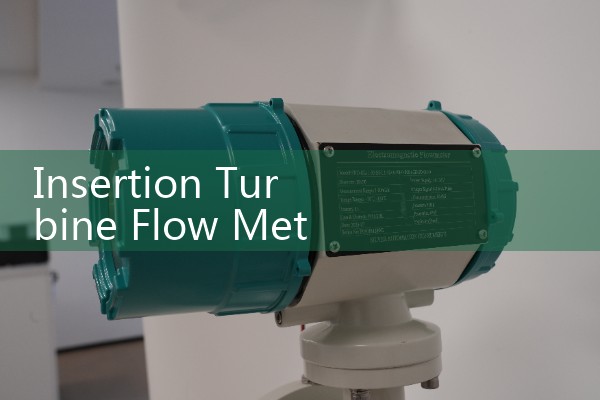
Pipe sizes from DN80 to DN2000 are possible. For smaller lines we recommend an inline turbine meter instead. The insertion turbine flow meter covers line pressure up to 40 bar and media temperature up to 80°C standard. A high‑temperature version handles up to 120°C.
How to Size and Order
Most engineers skip making a complex flow profile calculation. They give us pipe ID in mm, fluid type, min and max flow in m³/h, line pressure in bar, and temperature in °C. We calculate the insertion depth and the expected pulse output. For water mains, 0.3 to 6 m/s velocity is the working range.
Send us your pressure (bar), temperature (°C), pipe size (DN), and flow range. We return a quote with the right probe length, bearing material, and signal output. For hazardous areas we supply an intrinsically safe pickup and a Zener barrier for ATEX Zone 1.
Common Questions from Site Engineers
Can we install the probe while the line is under pressure?
Yes. You weld a full‑port ball valve to the pipe saddle. You mount the insertion mechanism on the valve, open the valve, and push the probe in. The sealing gland holds line pressure during insertion and retraction. Maximum pressure for hot‑tap insertion is 16 bar with the standard gland.
How deep do we insert the probe?
We calculate the depth from the pipe wall to the centerline or to average velocity point. For full‑pipe turbulent flow the centerline works. For partially filled pipes we discuss ultrasonic alternatives because turbine meters need a full pipe.
What maintenance does the rotor need?
Retract the probe once a year. Check the rotor for debris and bearing wear. In dirty water we recommend a schedule every six months. A spare rotor kit costs less than 10% of the meter price.
Can the adjustable probe work on viscous fluids?
Turbine meters work best on low‑viscosity fluids below 5 cP. For fuel oil or chemicals above 5 cP we recommend a Coriolis mass flow meter or an oval gear flow meter instead. Silver Instruments manufactures those too.
What signal does the meter send to our PLC?
The basic pickup provides a frequency pulse between 0 and 1500 Hz. Add a converter and you get 4‑20 mA HART. Pulse output works for batching and totalizing. 4‑20 mA HART fits DCS and SCADA analog inputs.
Get a Quote and Technical Sheet
Tell us your pipe size and water temperature. We will send a data sheet and price within one working day. For bulk orders in Southeast Asia and Middle East we offer factory calibration certificates and on‑site commissioning support. Contact Silver Automation Instruments directly.
Tel: +86-135-1213-1526
Whatsapp: 86-135-12131526
WeChat: +86 13512131526